Strowger Switching Demo Unit Project
This page is intended to be an ongoing log of the status of the Strowger switching demonstration unit being built as a display unit for the Telephone Museum of Prince Edward Island. From its beginnings, to the hoped for successful end, it will detail the progress as it happens.
Finding parts has been frustrating, and as February, many parts still are needed, but finally some of the basic items needed to begin construction are either here, or on the way. The following entry is the initial report, written as the construction stage started fitfully, then paused again awaiting parts, chiefly switch shelves. By Spring I will at least have a basic switching demonstration in operation. I will posts any further updates to this page, noting parts found, and construction notes.
Dave Hunter <[email protected]>
Main Telephone Museum of P.E.I. Page - https://www.islandregister.com/phones/museum.html
SWITCHING DEMO UPDATE, Jan 09, 2006:
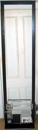
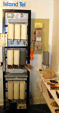
Aquisition of parts to construct a Strowger Step-by-step demonstration switch is proceeding, and a relay rack unit shown to the left has been purchased to mount the demo in. I have designed and mounted a lower shelf to hold the power supply and ring/dial tone generators, and as items arrive, they will be installed. I am over the hurdle, finally switching from a purely planning and acquisition phase to a construction phase. It is nice to finally make this transition, though there is much to find yet. A rack is being used rather than an angle iron frame, as it will allow for future expansion beyond the original configuration as time goes by, and as additional switches are found.A regulated 48 v 4.2 amp switching power supply has been found for the demo which will has been mounted on a home built lower shelf, as has a Tellabs ring generator which as been in the collection for some time. A power bar has been located on the right hand side to make the 120v connections.
Now, I am at a bit of a standstill awaiting the arrival of further parts ("Most Wanted" list posted at the bottom of the page). I will post photos as they arrive. I have found two selector switches, shelf jacks (which the switch units mount to), and a switch bank for one of the selectors.
Hopefully, I will be able to find either a couple 19" 3 switch shelf units (the item which physically holds the switch units), or a larger ten switch one which can be cut into 3 switch sections. This will save a lot of construction time. See updates below!
The card rack above the power supply will hold the ring interruptor (mounted), 10 vac transformer for powering the same, relays, dial tone generator cards, and other miscellaneous control and test circuitry. There is possibility this rack may be replaced by regular mounting bars when the dial tone generator arrives.
Having this switching demo will be very suitable in the collection, as PEI's first automatic switch was installed in Summerside in 1950 - a British Siemens Strowger switch. That switch remained in service until 1988. The Island's second, installed in Charlottetown in 1953 was a switch which was sold by Northern Electric, but which was actually an Automatic Electric Strowger Switch. I have been told the order went through NE, who drew up specs for it, then when it arrived from AE, they put their name on it. I am still looking for more information on this subject. With the choice of switching type in the demo, it will be true to the Island's past telephone history.
When complete, it will be possible to dial from telephones in the museum through this switch and see and hear as the Strowger switches connect to other phones within the museum. One will actually be able to experience a subset of the sounds of the Island's early automatic exchanges. It is still very much in its early stages, but will be completed as we can find the required bits and pieces. Though a huge project, it is a fun one, and one which will be very interesting to museum visitors. I will periodically post updates to the project here, and as construction moves forward will devote a full page of its own to the project.
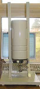
Left: The first item found for the demo several months ago now, was a Northern Electric Selector marked ED3286-31 GD WD NE-985D - yes, that is correct, a 4 digit ED number which I have been told since that this denotes a switch made for a PAX or PABX system. It is displayed on a test stand I built up to allow me to test out switches prior to permanently mounting them on the demo rack. Need docs for this switch.
Most items mentioned in this portion have been found. See later updates!
Received January 09th, 2006 - 5 shelf jacks and an Automatic Electric H-51301-A selector minus switch bank from Cliff Sullivan. Also received a couple of weeks ago from Cliff are a few wiper contacts and wiper cords The contacts are needed to replace the lower wiper on the NE and the AE switches which are damaged. This switch does have problems, but as of January 28th, the documentation had been located through another collector and will soon be on the way, which will make troubleshooting much easier.
Received January 10th, 2006 - a care package from Mike Magnus arrived, containing the bank for the NE selector, several more wiper contacts, another shelf jack for the test stand, and a selection of C.O. SxS tools. The switch bank has now been mounted on the NE selector shown in the test stand above.
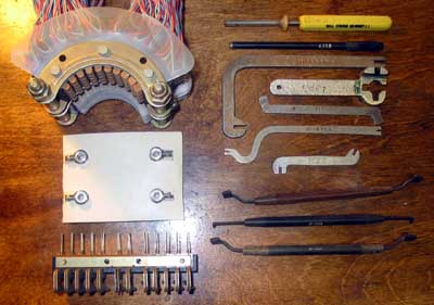
Shown immediately to the left, an assortment of various bending/adjusting tools from WE and AE. The top two are the wire unwrap, then wrapping tools. The following three tools were id'd by Steph Kerman: the third down is a double dog bender, the fourth, a tool for assembling the earliest type of wipers, and the fifth, an armature arm bender for SXS relays. It adjusts the amount of contact travel relative to the top of the armature when it is attracted to the core. This is in combination with the backstop position. Effectively it determines how far the armature sits from the core when the relay is released. The 6th and seventh items down are, in order, an armature stop bender, and a double dog bender. The bottom 3 are relay contact adjusters from N.E.
Also, today, a photocopy of an excellent Strowger training manual was received from Steph Kerman - he copied the entire manual and its many diagrams for a very reasonable charge! Thanks, Steph!
Several dial type gram gauges have been received from Leo MacDonald, along with a Neuses relay contact adjusting tool. Thanks, Leo! These will go great with the display of C.O. tools! Additionally, last week, three spring type GEC gram guages were received from Australia, and they, too have been added to the collection.
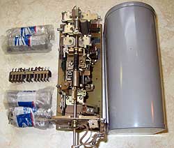
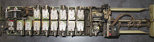
Received January 16, 2006 - a Western Electric ED-30903-30-G4-5-12 987-H connector switch complete with bank from Doug Vandegrift. The "make busy" switch which had broken off during shipping, and which I set behind the bank for this photo has been repaired and re-mounted in its proper spot on the left hand bottom of the switch under the bank. Docs for this switch have been found and soon will be on the way!
Update January 19, 2006 - All switches so far received have been tested on the test stand - the NE works fine after some fiddling, and everything on the WE connector has been checked except for the ringing, but alas the AE selector has a bad C relay. Thanks to Steph Kerman and Mike Magnus for their advice during this stage! Though recovering from a nasty flu at the time, I was glad to have this to work on - it helped to take my mind off the flu. Fusing and binding posts for the butt set, and of course a wire wrap shelf jack have been added to the test stand shown above to aid in testing.
January 27th, 2006 - The WE connector switch is now operational on the test stand with the ring generator connected, a butt set on its input, and a 500 set on the first position of the bank. Dial 11, and the phone rings; when picked up, there is talk between the two phones. Thanks to Mike Magnus for babysitting me through this process! An aggravating problem which occured the other day with the switch was solved this morning with a thorough cleaning of the relay contacts, after which progress was really made. This problem had resulted in a loss of horizontal stepping, resolved when I cleaned the contacts this morning.This was a small step for mankind, but a giant leap for me and for the museum!
February 03, 2006 - I heard today from Bill Smail that he has sent me a Lorain dial tone generator, its coil, some L/Co relays and mounting plate, eliminating some of the hard to find items formerly in the want list below!
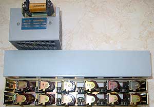
Feb 09, 2006 - The Lorain tone generator, coil, l/co relays arrived today from Bill Smail. Thanks again, Bill - they are just what the Dr. ordered. The relays are 2 stage AE relays, and when mounted, the offset contacts on one row of relays actually contact the cover. To solve this problem, most of one side of the cover has been cut out, and fibre insulators have been used below the cover to insure against shorting. A plexiglass window will replace the cut out side. The relay box needs to be wired, as the relays came seperate from the box.
February 15, 2006 - A Hendry HMW Flexible Type 70 Dual 8/8 Series Fuse Panel, Model FT70523FR has been purchased to protect the demo. It features Neg 24/48 VDC, Fail Alarm Connections, wire wrap, color telephone gray, 1.75" panel space, rack mounts 19 or 23" racks, and will protect the switches and electrical devices in the demo. A large number of the special indicating fuses for the panel have also been received...
Feb 25, 2006 - I had a visit from Don Price today who brought down a number of the items I will need for the project and whose visit eliminated a lot of the items still needed. He brought me several switches I still needed, as well as a number for parts, banks for both selectors (10 banks ea. in harnesses of ten), and some triple banks which were thought to be linefinder banks when they arrived, but which turned out not to have the required vertical commutator for a linefinder. These aren't a complete loss, as they can can be converted to use with selectors and connectors by the removal of one section. Last but not least, he brought a connector shelf which was able to provide me with enough shelf for 2 shelves for 3 switches ea. when cut to size. I will still need one more shelf which I believe is forthcoming from another gentleman to make the final shelf..
So, now mostly everything needed has been found. Tomorrow the construction begins in earnest!
Mar 02, 2006 - The two connector shelves have been mounted on the rack and a number of the switches hung on them. Since connector shelves are taller than one for linefinders or connectors, and since these shelves will be dual purpose, holding both lengths of switches, holes have been drilled in the blades of each shelf to allow a pin to be added in each bay to hold a shorter switch. Now comes the process of deciding the exact layout of the shelves and awaiting the other shelf before wiring can begin. There isn't much sense in wasting time wiring the switches, then having to redo the wiring as the layout might have changed. This is one of those times that patience is in order.....
The problem with the relay contacts in the relay panel above touching one side when the cover is installed has been solved - the cover has had enough material removed on the sides so that it clears the relay contacts.
Mar 08, 2006 - I got the fuse panel wired to the power supply yesterday, and now have the two connectors operating perfectly. It is now a demo - though somewhat limited in the number of digits dialed. One can dial the 2 digits assigned to the connector for the outgoing line, it switches up the bank to those digits, the phone rings, and can be answered. Both connectors work well. Eventually, one will be able to have two simultaneous conversations going on the demo, with the number of phones connected limited only by the maximum line size of the linefinders (100), and the number of line and cutoff relays installed. Currently, this is not a factor, as all calls are going only through the 2 digit connectors. Next step is to wire the selectors, and then the linefinders, ending up with the line and cutoff relays. By doing this, the machine can be tested all the way though the process.
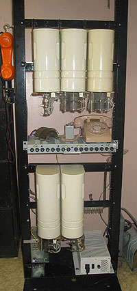
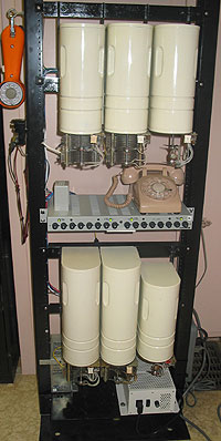
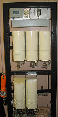
Bottom, power supply and ring generator. Lower shelf, connectors. 2nd shelf, 2 selectors and one linefinder. The indicating fuse panel is located between the lower and second shelf under the phone. When I install the final shelf at the top, the 3 linefinders will be mounted there, 3 selectors will be mounted on the middle shelf, and 3 connectors on the lower shelf. Top - not shown, the dial tone generator, ring interruptor and control relay, and the line and cutoff relays.
Calls are made through the butt set to the left for now, and received through the 500 set on top of the fuse panel.
Mar 10/11, 2006 - Yesterday and today, I spent doing a number of chores on the demo. First and foremost was to start wiring up one of my selectors. Along with this, I finally wired up my dial tone generator, so generously donated by Bill Smail to the project. It is nice picking up the set and now finally hearing dial tone. When I had first mounted the dial tone generator in a panel at the top of the switch, I inadvertently caught its external voltage dropping resistor between the unit and the panel, cracking it. I have replaced the cracked resistor with a new 10 watt one. I had some problems getting the selector working at first, but it appears to be working well. At present, one has to dial three digits to ring the phone, but when I get the digit absorbtion on the switch set up, that number of digits dialed will increase to 4.
Evening - Early evening the 11th, I re-installed the previously removed d.a. comb on the selector. It had been removed to simplify testing of the switch. With it configured as it is now, it ignores the digits 2 and 9, with the result as I have the numbers set up currently, should I dial 2311 or 9311, the switch will complete the call. Should I dial any first digit but 2, 3, or 9, the switch will step up to that digit, rotate to the right looking for a connector, then drop when it reaches the 0 position. So, the end result, is that it ignores the first digit so long as it is a 2 or a 9. I believe what is causing it to do this is that the two tabs on the left hand side of the comb are bent out. Some time, I will bend out another tab to see if it adds that to the list of ignored digits (result of bending out the 6th tab is that 6 has been added to the ignore list, so this is confirmed).... Anyway, the long and the short of this is that the switch will now accept 4 digit numbers, so long as the first digit is a 2, 6, or a 9.
Mar 12, 2006 - A second selector/connector path has been activated and tested on the switch. I am driving my wife and dog crazy by ringing through on the switch. The dog when my parents had her, taught her to bark every time a phone rang or that someone is at the door, and you can't teach a old dog new tricks, so every time the phone rings, it is VERY loud. This is what, following a suggestion from a correspondent, we are going to refer to as a "K-9 Extension Ringer." :-)
Mar 13, 2006 - Not a lot of change today, but with the help of Mike Magnus, the d.a. comb has been fully doped out, and the digit absorbtion has been set up to absorb repeatedly, with the result that a number such as 229-2311 may be dialed on the switch - the 2's and 9 will absorb, and the final 3 digits, 311 will dial through to the phone. What it amounts to, is that if only the tab on the left of the comb is bent out, the switch will absorb repeatedly. If right tab only is bent out, it gives level to 11th position, returning busy (overflow). If both left and right corresponding tabs are bent out, it will absorb only once, as was the case at first before bending the right hand tabs back in.
Mar 17, 2006 - A new shaft and switch for one of my linefinders has been received today from Paul Wills, as well as a number of both vert. commutator and normal wipers and cords and a new vertical interruptor contact assembly for one of my finders.Thanks, Paul. This has fixed up the two best ones I have, and also brought a third back to operating condition. Still needed, banks fo fit them. If only a 200 point bank can be found, I can remove the lower level to produce banks to fit these. They must, however have the vertical commutator strips needed for line finders. Hopefully someone will have a strip of two or three.
Mar 19/20, 2006 - Still no linefinder banks found. Over the weekend, two Automatic Electric H-580288 selectors purchased from Doug Vandegrift some time back were cleaned up and lubricated, damaged wipers and cords replaced, and their basic functions tested on the test stand. These were brand new selectors which had been stored outside in their boxes for some years and which had suffered mainly water damage. This affected mainly the cover, which suffered some surface rust and had to be painted, and the cloth covering on one of the switches wiper cords had rotted off. Other than that and requiring cleaning and lubrication, they were in excellent mechanical shape. The major problem getting them going was figuring out the jumpering on their vertical commutators - yes, like a linefinder, these selectors had vertical commutators, but unlike linefinders, the commutators were part of the switch body itself. As they had never been used, these jumpers had never been installed. They are 100% functional now. This was a fun little weekend project while I awaited the linefinder shelf and try to find linefinder banks with the proper vertical commutator strips.
Mar 21, 2006 - My linefinder shelf is finally on the way. It will take a week to ten days to arrive, so in the meantime will busy myself with other tasks and continuing my search for linefinder banks....
Mar 24, 2006 - All of the switches have been lubricated properly for the first time in many years, although some substitutions had to be made with lubricants, hopefully with equal or better products. A document detailing the proper lubrication of these switches was received the other day from another collector. One of the lubricants, Oildag, used on the ratchets and ratcheting surfaces on these is quite hard to find in small quanties. It is a graphite/oil suspension. I tried a couple of substitutes, finding one better than the other. The first is called "Lock-Ease", a graphite/petroleum distillate designed for lubricating locks. It however, put on a very sparse, uneven coat, so I tried another product available in Home Depot stores, Jig-a-Loo Graphite Extreme. It is a spray product, and of course can't be sprayed onto an item such as this, but by spraying into the cap, then using a #4 artist's brush to coat the spindles, etc., I got an excellent, thin, even coat of graphite applied. The petroleum carrier evaporates after application.
The other bearing surface according to the original lubrication document were to be lubed with a spindle oil, a refined, non-blended neutral petroleum oil, and with a blended lubricating oil. These were substituted with 3-in-One oil, a good general purpose light machine oil. After lubrication, all switches sounded much smoother as they operated. Under the light type of service these switches will receive, lubrication will be needed only rarely, but they did require lubrication now, after years of disuse.
Mar 25, 2006 - The preparations for moving the demo over to the museum have begun. All materials such as spare parts, fuses, selectors and connectors, spare selector banks, etc. have been moved over. The actual physical move of the switch itself will take place after the shelf for the linefinders arrives, as the tools needed to modify it for use on the rack are over here. Once it arrives, it will be installed, the switches will be removed for the move, then bank holding plates installed. Once safely over there, the plates will be removed, and the individual switches re-installed.
Mar 29, 2006 - The linefinder bank problem may be solved. I will post here when I know for certain!
Mar 31, 2006 - The shelf for the linefinders has finally arrived this morning, and I have it cut to fit the rack, and its mounting brackets fabricated.
A funny story to tell about this. As I cut the shelf to size using a hand grinder and cutting disk, my shirt started feeling very warm. It kept getting warmer, and I looked down, I saw my shirt on fire, lit by the sparks from the grinder. Nothing serious other than a 4 inch hole in my shirt, and correspondingly well cooked flesh where the hole was. I could just imagine my obit. in the newspaper, "Death by Strowger."
Now, the next chore is to wire up the linefinder shelves and to wire the relays. It looks as though we have overcome the linefinder bank problem. I will know for certain soon.
I have a third linefinder and selector to place on the lower two shelves, and in the photo to the right, the lf's have been moved to their final resting place.
I need a long cover for my third connector. Both selectors and connectors already installed are wired. Blank selector and connector positions (shown in the left photo with linefinders in their place) still to be wired.
Apr 03, 2006 - The last few days project has been wiring up the line and cutoff relays. They were all supplied unmounted, and I had to interwire all the relays, and then adjust them so that all work properly. They are the two stage l/co AE relays, and their adjustment is very tricky. Now, however, they seem to be working quite well. The 25 pair cable from the relay box will lead down to a 66 block, where all the interconnections to the banks, linefinders and connectors will come together... Next step, getting the linefinders going once I have the banks...
Apr 04, 2006 - After checking out all relays last night and adjusting them, I finally got to the stage where I was ready to re-install the relays in the demo rack. First, I connected the nether end of the 25 pair cable to a 66 block to make interconnection to the linefinder, connector, banks, and lines easier. I deliberately left the cable long, coiling the excess up and tying it with nylon ties, to assist should I ever have to take the relays off the rack for more adjustment, etc. This is a job I had been putting off, as the wiring when viewed whole is quite complex, but when I actually started doing it, one relay at a time, it wasn't as bad as I had thought. So, another large leap for Dave Hunter, and a small step for mankind.
Apr 15, 2006 - I realized today that an update is long overdue on this page. In the past couple of weeks, I have been at a bit of a standstill awaiting a few small parts. Chuck Richards has come up with a solution for mounting commutators on a regular bank, to convert it so a linefinder bank. He is also providing me with 2 commutators. I have received a sample of a pin, spacer, commutator set, and we are just awaiting the final commutator from John Jones to make sure its mounting holes are the same before Chuck sends me the final two conversion kits, just in case the last kit might need to be modified to fit the commutator from John...
Three strings of new banks have been cut for the switches on the demo from the triple banks brought by Don, and one level has been removed from each. These banks are in much better shape that the other banks I had (far less contact corrosion), and I have left them connected in strings of three which will make the final wiring much easier, rather than using the bare banks I had used previously. On the side of each, long leads have been left to make connecting them to the demo much easier. I will be able to connect each wire to the switch using ScotchLok™ connectors. One string of banks will have its pins removed on the right hand side, and have the modified pins/spacer/commutators which will convert it to a linefinder bank. One bank on that string has already been converted.
Another item being worked on is a third connector. There were two connectors which had been brought by Don in very bad shape. This didn't matter as they had been brought solely for use as a parts supply. However, I thought that, in part to educate myself, and to supply a third connector for the switch, that I would attempt to rebuild one. These had been stored without covers, and had their shafts bent, relays knocked out of adjustment, and a number of relay contacts bent. The top spring was missing off the shafts from each. In a trade from Doug Vandegrift in exchange for some jack strips, light strips, and spacers from my spare 555 switchboard, I was able to acquire a new shaft, new spring, and a number of other useful items.
I picked the better of the two and began to rebuild it. Much to my amazement, it now works, after much relay contact bending and adjusting, replacement of the shaft, etc. A cover is being send by Fred Haynes to replace the missing one on this switch. I could have done without this switch, but it was worth its weight in gold for what I learned from it about servicing switches, and though the demo would have been a very effective exchange without it, it merely increases its capabilities.
Construction on the switch will proceed further when the bank kits and commutators are received. Meanwhile, I will keep working at those little refinements I have been meaning to do, but have been putting off!
Apr 19, 2006 - I am finally in the process of moving the switch over to the museum buildingfor the summer. To lighten it up, all switches have been removed and those banks currently wired have been placed on hangers. By doing so, it has lightened the rack by at least 50%. The actual rack will be moved towards the weekend, when I have my son here to help, then the switches will be re-hung. Construction will then proceed again.
Apr 21, 2006 - The demo and its rack have been relocated to the museum building, and work will soon resume. All components have been re-mounted, and the system is being checked for proper operation. All signs show it survived the move well. Work on the switch will resume soon! A cover for the third connector was received this morning from Fred Haynes. Thanks, Fred!
In the end, with the equipment which has been found for the project, it will be capable of connecting 12 phones, with three paths through the switches. In other words, 6 phones could be talking through the switches at any one time. Some day, touch tone capability may be installed on the switch. Not too bad for a compact demo made from 50 year old parts.
May 03, 2006 - The connected set of banks has been installed on the selectors, and I am awaiting the final two posts and commutators before mounting the linefinder's 3 connected banks. All issues pertaining to the l/co relays have been resolved, and a 554 set has been mounted on the switch for demonstration use - the butt set has been left on the switch till I get the linefinders working, and the output phone is on the shelf to the right.
May 05, 2006 - The long awaited commutators and posts have been received and they have been installed on the linefinder banks, and these, in turn have been installed on the demo. I hope to get a chance to hook up the finders some time this week if all goes well...
Oct 26, 2006 - As you notice, work on the switch has been suspended for the summer months, bacause I don't want to take the switch out of service for any length of time to get the linefinders and relays connected. This will take some time, and I want to keep the switch operational for demonstrations this time of year as summer visitors arrive to see the displays. It has been of major interest to this year's visitors.
However, planning continues, and come the end of the visitor season, I will again return to work on the switch. Acquired and received this week (Sep 26, 2006) was a trouble lamp designed for use in a central office, which clips onto a rack and was used for lighting up those dark corners of an exchange. I forgot to mention when they arrived, but some time back, I received a fairly complete set of Strowger switch tools, including gram gauges, spring and relay contact benders and burnishers, specialized tools of all sorts, and which also came with two brand new replacement bulbs for the lamp mentioned above. At the same time as the Strowger tools were found, I also found a set of tools for servicing teletype equipment, and an Automatic Electric Loop Leak Tester.
Nov 22, 2006 - In preparation for the winter, the switch was moved yesterday over from the museum by my son, after all switches being removed, and today the switches were re-installed one by one, and the demo's operation thoroughly tested. Work will continue this winter to activate the linefinders and the l/co relays so that a butt set will not have to be used to operate the switch. I will post updated once this work begins. I will be laid up for a while following an operation to put a plate in my foot to repair damage from an unhealed break which occured last year, and with the switch handy, it may be a good time to do a little bit at a time on it. At least with it back here in the house, it will be possible to do this with limited mobility.
Nov 23, 2006 - 35 more switching tools have been received and have been cleaned up. In the few days following, I inventoried all my switching and teletype tools (100+ now), and have listed them in a document along with their design uses using information from listings in Bell Telephone Labs Tool Catalog X-65518-01, issue 14, April 1, 1932, and from Automatic Electric Technical Bulletin 150-540, issue 10, and Teletype Maintenance Tools, Teletype Corporation Section 570-005-800TC, Issue 6, Aug. 1977. This gives me a much better idea of which tools I still need to get, and offers a quick reference as to what each tool was designed to do. Of course, each tool had purposes beyond their designed useage, and there are ways to do those jobs without the correct tool, but it is really nice to have the "correct" tool for the job. If anyone would like a copy of this document, you can download a copy from the telephone links page. Even though this was a document done up mainly for my own convenience, it has turned out to be an interesting guide to the more comon switching tools.
Nov 28, 2006 - Having survived the surgery, I am hoping within a few weeks to be feeling well enough to get back to work on the demo. Much of this will be able to be done from the wheelchair, and the items I will need are located within arms reach. I will have to wait till it is safe to stand on the leg for a short period of time.
Jan 02, 2007 - Back at it, still with very limited mobility, but it has been driving me nuts to have the switch here, and just no be able to do anything with it. I was given the all clear to put a limited amunt of weight on the cast on the 28th of December which frees me up to do a bit. All leads on the three sets of banks have been identified, the first two lines worth of ring and tip plus c wires from the linefinder connected to the relays, and the connector banks with the first two lines ready to punch down in the morning, all relays operating properly, and a phone connected to line 1 and 2 with both phones keying the relays properly. I am of course taking my time and the work is slow going, but nice to see it progressing again! Once the linefinders and relays are operating, I will set the demo up to run more lines.
Mar 28, 2007 - Ok, I had had great expectations and plans for the demo this winter, but ran into severe problems with both my health and with the linefinders I have, so I couldn't get nearly as much done as I had hoped for. All linefinders were severely damaged when received - of course, I can't complain - the price was right. However, at one point they had been shipped in the back of a dump truck, with resulting damage to shafts and severely bent relay contacts. With work, I am sure that they can be repaired, but first it will help to be able to use a working unit to confirm the wiring is correct (which I am sure it is). I have been able to confirm that the l/co relays are operating properly, but the best semi-working linefinder I have appears to be stuck and going only to the second line, whether of not, the first or second line is active. So, I will wait till I find a known good linefinder before tackling the addition of the finders again. Once I have one working correctly, I will tackle troubleshooting the finders I have. I have returned the demo to a state where I can demonstrate it without the finders and have the switches dismounted, and the unit is back on the moving cart ready to go back to the museum as soon as I can get my son to move it over. This will ensure that the demo may be used for this season. If during the year, I am able to find a working finder, the unit is ready for an easy conversion to add the finder.
Mar 31, 2007 - The demo is back in the museum, thanks to a visit from an unsuspecting Jeffery. I have all the switches remounted and it is ready to go for the season! It is nice to have it back where it belongs. Prior to Jeffery's arrival, I had all switches removed and waiting in the museum, and had the rack itself mounted on a furniture dolly. Beyond the move, it only took a couple of hours to remove all the bank hangers and to reinstall the switches and re-align the wipers on the switches.
To see the demo in its museum environment, please see my Museum Page!
Various pieces of documentation have been received from a number of members from the TCI and Strowger lists, and your help is truly appreciated!
If anyone has items or information that will help in the construction or display of this switching demo, please let me know. I want to thank all who have contributed parts, and/or advice for this project. As the project moves forward, all will be acknowledged with thanks. Upon the completion of this project, if any parts remain unused, they will be re-offered to the collecting community at cost in case they can help with someone else's switching project.