U.K. Strowger Switching Demo Unit Project
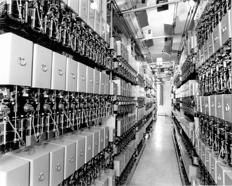
This page is intended to be an ongoing log of the status of the UK Strowger switching demonstration unit being built as a display unit for the Telephone Museum of Prince Edward Island. In 1948, Island Tel ordered a 1200 line Strowger switch from ATM of Liverpool. It would become PEI's first automatic switch. It arrived in 1949, and was activated February, 1950. It served the community until 1988 when the long-lived exchange was cut over to a new DMS-100 switch.
Dave Hunter <[email protected]>
Main Telephone Museum of P.E.I. Page - https://www.islandregister.com/phones/museum.html
For years, I searched for left over items from this exchange. but little was found. When the switch was de-commissioned, most of it was scrapped - what hadn't been was taken to Newfoundland to use for spare parts for similar equipment there. In April 2012, I was contacted by a gentleman, Earl Pauley, who had worked on the changeover to DMS-100. In 1988, he had saved five of the switches from the exchange, and he donated them to the museum a few weeks ago.
The best way to show these switches is in an operational display, built using original Summerside switches. A plan for building such a display then ensued. So, this will act as the perfect commemoration of the original ATM supplied switch. People will actually be able to see these switches in operation, and it will actually ring phones. Aside from photos of the 1950 switch and its 1988 successor, I also have a commemorative plaque commemorating the change-over. It will be hung over the demo unit.
It will be learning curve for me, as I have never worked at all with UK switches. There are some major differences as compared to North American switches.
Before beginning construction many support parts had to be found, a power supply, ring generator, rack, switch supports and shelf jacks, a fuse and alarm panel, and line and cut-off relays.Many of the switch supports, shelf jacks, etc. were located thanks to John Mulrane who sent them from Ireland. These parts are mosly as old as the actual switches - not easy to find. Most parts were located by the end of April, and placement on the rack is beginning. The most difficult part to locate was the Vertical Marking Bank (Vertical Commutator as it is known here) for the line finder but it was found April 21, 2012 and donated to the project by Colin Butterfield..
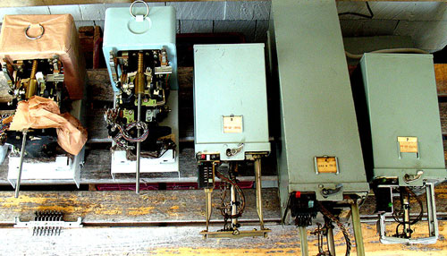
Required parts had to be found as far away as the UK and Ireland. Here are photos as the switches as received:
Switches with Covers on.
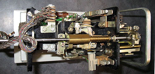
AEI Linefinder (2 of these NOS from the exchange spare parts)
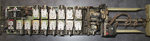
Selector
Another Selector
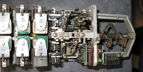
Unusual 10 party Final Selector (Connector) This switch was in use to support the Miscouche lines.
The Build Begins!
'The Build' began April 20th, the day the rack finally arrived. The rack chosen was a 19 x 44 inch high aluminum relay rack - large enough to carry the full demo, but not too large to leave huge blank spaces. The UK switches mount differently than North American Strowger switches. The UK system uses bank hangers which sit on a 1 x 2.5 inch channel. As this isn't a common size anymore, I had a 20 inch section made at Livingston's Metals in Charlottetown. I picked it up in the afternoon. They were slightly large in the 1 inch dimension, and had to be trimmed down so the bank hangers would fit - the ends were cut to fit the rack.
I am in no rush to get the rack ready for wiring - I am shooting for the 1st of May for the wiring to begin, so I will take my time and make certain, each part is located in its optimum location on the frame to make the job of wiring easier..
I really have to say I had to force myself to do anything today because of the Flu, but I wanted to get started.It wasn't great progress, but at least, it was some.
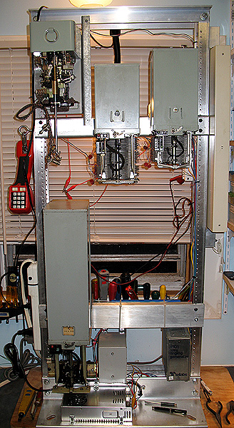
First day's work mounting switches. I still need another section of 1 x 2.5 inch channel to mount the connector or final selector. It will mount under the linefinder or first selector on the left. The l/co relays will mount on the right. A second selector will mount in the empty shelf mount on the top row.
Apr 29, 2012 - After a week of the Flu and other things, not a lot of change until today. The switch has all the switch mounts installed, but with the switches off as I work on other things.
The lower switch mount is on now for the tall party line Connector (Final Selector), the 48 volt 7 amp switching supply installed, fuse and alarm block installed over the power supply, and the ring generator in place. The l/co relay strip (beige) is mounted on the right. To mount the imtermediate selectors and final, it is just a matter of clipping them into slots in the mounts and letting them settle. Of course, I will want to first install the banks on the upper three switches. The mount for the Pre-2000 linefinder is more like our North American mounts, as are the banks. The Vertical Marking Bank, or Vertical commutator fastens to the right hand bank pin. The most time consuming part at this point is fabricating the mounts for everything, and planning a layout which will keep things as compact as possible.
Later on, I went back to mount the banks and got that chore completed.
May 11, 2012 - The past week, I have been busy setting up the C*NET VOIP server, etc.in the museum. I plan on returning to the switching project tomorrow!
May 12, 2012- I began by stripping down the banks for the two selectors. I need two, three, and 4 levellevel banks for these, and currently all these banks are three level. I removed the bank bolts on one, and discovered that they are only threaded down to the third bank, so it won't be a simple matter of cutting them down. They will either have to be threaded further down the bolt using a die, or replaced. As they are a less than common UK thread, it looks as though replacement will be my only option. I have some 10-24 stainless rod which should work as a replacement, but need to get more nuts for it first. Then the bank can be re-assembled in the needed configuration. So, we will have to pick up some nuts to fit later today before more progress can happen.
We had company for much of the day, but I got over in the evening, and got the two banks re-madel, using bolts made from the stainless rod. These are assembled, and back on the switch..
May 13, 2012 A.M. - A power bar was added to the left hand side of the switch to handle the AC lines from the ring generator and power supply, etc. Wires were tidied up. Later: a bracket has to be fabricated to mount the right hand side of the fuse and alarm panel (located above the power supply, and attached on the left hand side to the rack).
May 13, 2012 P.M. - this above mentioned bracket was built and installed, and the wiring between the 48 volt power supply and the fuse and alarm panel above it was done. It is now at the point where the next step is to have the ex-Island Tel switchmen down for final wiring and assembly.
Jun 05, 2012 - Earl Pauley will be down tomorrow afternoon, and we will do some of the wiring on the switch. Earl was one of those who worked on these switches when in Summerside, and was the gentleman who rescued these switches in 1988. He has kindly offered to help out!
Jun 07, 2012 - As mentoned above, Earl Pauley spent the afternoon and we accomlished some on the demo switch. Our limitation was the documentation we had for the switches, which was nearly none, so basically what we accomplished was to hook up the +- 48 volt DC to each switch... We need to get more information on the switches, since, as one would expect in the years since Earl last worked on these switches, memories fade. Alas, back when he rescued the switches, he didn't think of rescuing documentation. So I am searching for some more information on the shelf jack wiring and on an allotter for the linefinders. As soon as we have the information we need, we will move forward.
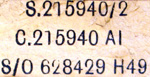
For those of you who might have a source of information the swiches are as follows:
The AEI linefinders are marked XT13730
The Pre-2000 type selector is marked 204733
The 4000 type selector is marked 234951
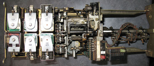
The connector is a ten party line connector labelled as follows. In addition to the usual components of a connector, it also has a rotary switch in the top which does switching for the ten parties on each line. I have been told these weren't used in England but were made primarily for the export market: Jun 08, 2012 - The two selectors were lubricated and the relay contacts cleaned with some improvement. Unfortunately, these units have been sitting idle since 1988, and have developed problems due to storage. Photo to left of it today. Banks are removed during testing.
Jun 09, 2012 - To assist us with information, I have ordered copies of two books from used book stores in England, Herbert and Proctors "Telephony: a detailed exposition of the telephone exchange systems of the British post office, Volume 2" and the later Atkinson's version of the book, also "Telephony: a detailed exposition of the telephone exchange systems of the British post office, Volume 2".Herbert and Proctor covers pre-war designs, while Atkinson covers post-war. Between both, I hope they will provide us with information which might be of help. While Volume 1 covers chiefly the phones of the time, Volume 2 covers the central office automatic exchanges and their design. That is why only Volume 2 had been ordered of each book.
Jun 22, 2012 - The two books mentioned above have arrived, and they are a wealth of information. At long last, we have a dial tone generator, a Lorain F1 purchased from John Jones. It also arrived today. In the past few days, the interruptor had been set up on a metal plate which mounts just to the left of the ring generator, and the dial tone generator will mount to its left.
Aug 07, 2012 - There has been quite a bit of time since I last worked on the demo thanks to my setting up a router on the VOIP system below to allow the system to control calls into the North American Strowger switch and eventually this one. See the story of this router in the C*NET portion at the bottom of this page.
The problem I have been having with most of these switches, is I could get the shaft to move up one, and sometimes two levels at best, and then I couldn't get then to raise any higher.... Now, since they all did this, it was really puzzling me. Finally I had a "Eureka" moment. I think I hit the nail on the head. The power supply was rated at the correct voltage, and could generate more amps than required by the switches (7A). But the supply was losing regulation during pulses (transient voltages from the relays) and the lower voltage during pulses was enough to keep them from operating.
To solve this and smooth out the voltage, I put a HUGE electrolytic capacitor on the supply output (something like 10,000UF), also physically large 4 inches x 10 inches. It seems to be smoothing out the transients well. I had been pondering this for a while wondering if it might be leading to the symptoms I have been seeing.
I hooked up a butt set this morning to one of the selectors, and now it will go all the way to the top, whereas before it would go at best one or two digits. I don't know yet if it solves all the problems, but makes it a lot better...
Aug 08, 2012 - We are back in business, now with the power supply output smoothed out. This was a frustrating problem, and went undetected to this point since the measured output (48 VDC) on the power supply didn't appear to fluctuate off its design 48 volt, 7 amp output when measured by a digital voltmeter. However, the problem did show up when viewed by an oscilloscope. Today, I checked out the other selector with the butt set on its input, and, it too, is working with the power supply output smoothed out. It is amazing how much a little problem like the power supply problem could cloud the issue - the solution really so simple, and had made such a difference in the way the switches were working.
I have wired the capacitor in permanently, and have it strapped onto a cross-bar on the demo. I still want to place a bleeder resistor across the capacitor contacts so it won't stay charged with the supply turned off. A few days ago, I had to steal the ring generator off the British unit temporarily to replace a faulty one on it - I have since repaired it and installed it back on this demo. I am hoping in the next couple of days to get the connector checked out, then can begin wiring the two selectors and the connector together. Once that is done, it will be a basic demo unit, missing only the linefinder. Then comes hooking up the l/co relays and the linefinder.
Aug 09, 2012 - First thing today, I checked out the other selector - it too, is now working well with the modified power supply. A bleeder resistor was placed across electrolytic capacitor added yesterday. I then decided to install the Lorain dial tone generator next and hook it up. I picked up some brackets and nuts and bolts from the hardware store and completed the job around 4 p.m.
Aug 10, 2012 - I didn't get a whole lot done, but did mount a 66 block on the demo to make troubleshooting easier. Lines were run from it to the inputs for each selector, which makes it a lot easier to clip a butt set on the selectors for testing... A number of other minor things were accomplished as well.
Aug 15, 2012 - The creature stirs! Today, I connected release earth to the two selectors, and have them stepping upwards, hunting across the banks, then releasing as they should.
I still need to find a heat coil or time delay fuse to protect the power supply from release failures hence the clip lead before making that connection permanent, but it is well on the way and the two selectors are working! Installing and wiring up the banks next. We thing we have this problem solved - I will fill in details later.
Aug 16, 2012 - Not much got done today for various reasons. Still looking for heat coils or time delay fuses for the release earth lines to the switches, and a slight problem crept up in one of the selectors. I did mount a ring on the side of the rack today to clip my butt set on while working on the switch. I did this on my other demo when I built it, and have found it very useful through the years.
Aug 17, 2012 - The morning began with a phone call to John Mulrane in Ireland in CNET to discuss plans for the switch. John has offered to design the line and cutoff and linefinder control circuits there. I then moved on to the connector. I ran into problems with a twisted shelf jack and spent a very long time unsuccessfully to ge it straightened out enough to make it mate with the switch properly. However, it is looking as though I may need to find another to get it to work properly. Work will continue later on.
Aug 18, 2012 - Today, I decided to try out the 10 party line connector. It is in poorer shape than any of the other switches, being one of the earliest switches from the Summerside exchange. When I first applied power to it, it was blowing fuses shortly after the power was supplied. Eventually, it failed completely, in a puff of smoke. A selenium recitfier used for spark suppression had gone bad, as they are known to do. I replaced it with a 1N2006 semiconductor rectifier mounted on a terminal strip. While doing this, and examining the switch more carefully, I discovered some the capacitors were leaking, and that everything was coated with black soot along with all its contacts. Later checks showed the capacitors still working despite the bit of leakage.
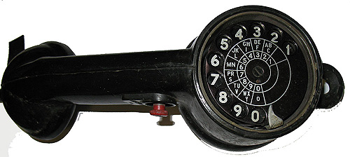
Aug 19, 2012 - Just a random thought. I have been using a modern butt set with the demo as I set it up. What I really should have used is the NOS vintage UK butt set shown below which also came from one of those who worked on the Summerside exchange. It will be perfect with the demo. It is a huge butt set compared to others - more fitting to be used as an offensive weapon!
280HA70 Butt Set
I spent a while this morning burnishing the contacts on the final selector (connector). It doesn't make it work any better, but is a step that is necessary since it is in such poor shape. I am still considering the option of trying to replace it with one in better condition ( not necessary as we finally got the switch working well - see below..).
Aug 20/21, 2012 - Days spent locating packing materials to send one of my linefinders over to John Mulrane so he can fully test the line and cutoff and control circuits he is building for the demo. The last of the packing materials were bought Tuesday morning, and it is now packed pending shipment.I spent a lot of time figuring out the best packing, as my greatest fear is that the switch might become damaged while on the way. This is a brand new NOS switch, never powered up from the exchange spares.
Aug 23, 2012 - A frustrating day working on the 62 year old connector switch. It has a number of problems and is proving to be a real headache...This switch is one of the original switches from the Summerside exchange. When the number of party lines in the Miscouche area were reduced from 19 party to 2, it was removed from service and placed in storage. So, it had many years to get in the shape it was in when it came. All the rest of the switches are later additions to the exchange, including the two linefinders which has never even been used and which were spares for the exchange.
This switch suffered from deterioration of some of its parts which have been replaced, bad contacts on relays, a coal like soot which covered the entire assembly, and dirty contacts, as well as a copper oxide rectifier which was shorting, and since replaced. While working on the switch I was constantly cleaning areas to get rid of most of the soot. Once I finish this switch, final assembly of the demo can take place, and then the only hold-up will be waiting for the linefinder and control relays to return from Ireland.
This is a very unusual connector - those in the U.K. where it was made, have never been seen one with the ten party modification, as the U.K. never had more than two parties on a line, but they were made for the export market. This switch has a german 10 party uniselector mounted on it to serve the 10 party lines as identified by John Mulrane, and is basically an ordinary GPO final selector, modfied for local requirements. Therefore, I am very happy that it is coming along, and I hope I will be able to get it working because of its unusual history. Alas, its unusual nature makes it impossible to find documentation showing the modifications made to suit the need..
Aug 27, 2012 - A much more successful day. I discovered today that a plug in the test jack on the switch had come in the wrong position, and when I returned it to the correct position, found that it was much easier to set the switch up. It is now responding to input, and only a couple of minor remaining problems to solve until it is fully operational again.
Aug 30, 2012 - The linefinder left for Ireland today finally. This will allow John Mulrane to test it out with the relay set he is building for the switch. I had been trouble getting DHL here to pick it up - finally it happened today. I lost a lot of time working on the switch this week since I was afraid I would miss the courier if I was working in the museum. But its gone, and now, back to work!
Aug 31, 2012 - Earl Pauley called this morning and came down at 1 pm today, and we worked at the demo until suppertime. We have all the switches working (except for the linefinder), and we have the banks mounted on the two selectors. They are also wired so you can dial through the first selector into the second, and from there on into the connector. The only thing not 100% solved is getting the extra rotary 10 line switch, a modification on the connector for some of the badly overpopulated party lines in the area working. Of course, we will eventually get that part operational. The switch will take 5 digits, one for the first selector, one for the second, and three for the connector. It was a lot of progress for one day! Thank you Earl, John, and everyone else who has contributed with parts and advice on this build!
Photo of demo switch after today's work [left].
Sep 01, 2012 - Time was spent neatening up yesterday's wiring, replacing runs done temporarily with clip leads, putting wire ties on to keep wiring neat, further testing, and replacing covers. Switch interconnections are run to a 66 block to simplify testing and facilitate interconnection for the future.
Sep 02, 2012 - It has been pointed out by John that the failure of the rotary switch in the connector to operate may be normal - When you dial a number on the final, until you have line relays it will test the line as busy and won't go any further. This may be the reason why it won't step the uniselector. If you connect a 1300 ohm battery to the 'P' wire of any line and dial that number the FS should switch to the line you have dialled. It should then in theory be possible to dial the party line number.
Thanks, John for the suggestion. It sounds like that is exactly what is happening. So, essentially we have a fully operating switch now, minus of course the line-finder control unit and l/co relays.
The bank has not yet been placed on the connector since the shelf mount I have for it is twisted, and the bank will not align up with the switch correctly - we need to find one more good bank mount. It also affects the alignment between the switch and the U-points, but we have it fitting better there than at the bottom of the switch. Both problems will be solved when I get another mount to replace it. Try as I might, I have not been able totally straighten it out.
Sep 03, 2012 - The linefinder I had sent over to Dublin arrived there safe and sound this morning. I had been worried it might get damaged, so packed it like a brick out-house, overpacked, but well protected.
Sep 04, 2012 - Not a lot achieved today - last night our water heater split its sides, and spilled all over our basement. I found a few minutes during the day to get away from the mess in our house, and to move the connector up in the rack to make it easier to access the fuse panel when the banks are installed on the switch. Had I not done so, it would have been very difficult to change fuses. To do so, it was necessary to exend a couple of wires. The rest of the day was lost to the cleaning up after the disaster next door. Thankfully, the plumbers got here quickly to install a new heater.
Sep 16, 2012 - John Mulrane is trying to obtain some drawings from the GPO archives, so until he can locate these, and get the relay set built for the linefinder, there isn't a lot I can do with the project. All here is in running well, and in the meantime, I am working on ither projects until John can get the drawings. I will give updates whenever they are available...
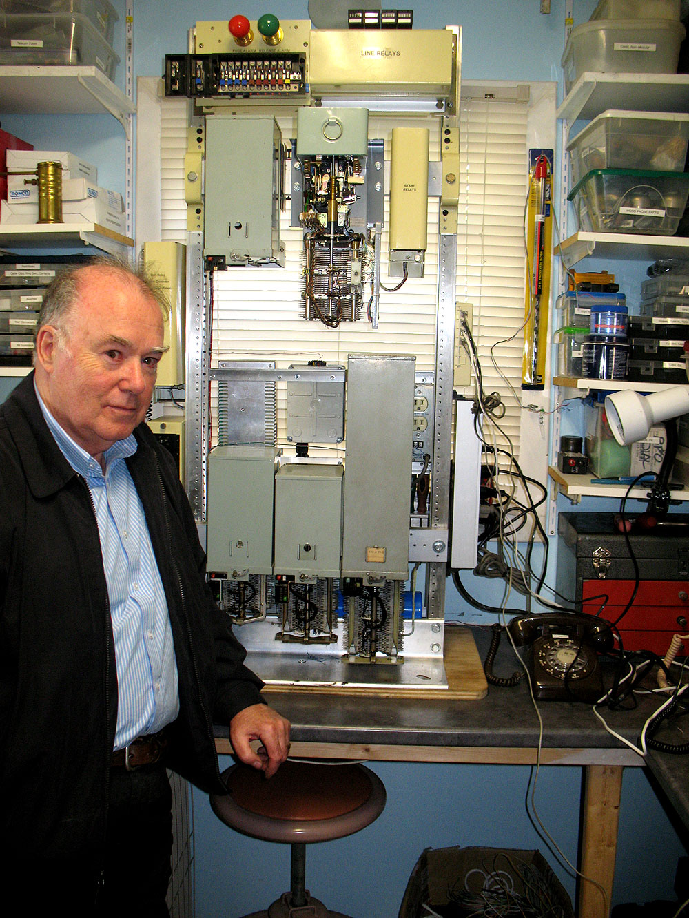
Jun 08, 2015 - It has been a long time since any updates, and a lot of water has flowed under the bridge since the last one. The switch is now complete!
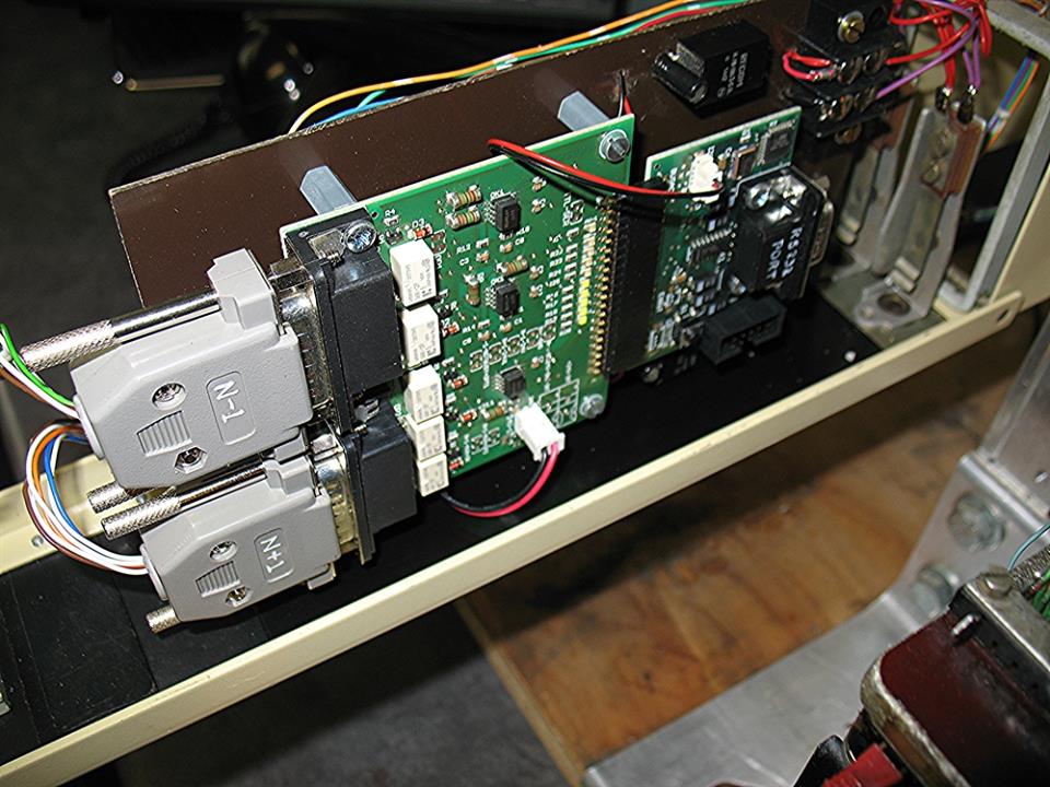
As mentioned above, John Mulrane has made huge contributions to this project. In the end, he not obly designed the relay set for the line finder, but also redesigned the alarm and fuse panel, then a microprocessor controlled cadence generator, and tone generator.
For best fit and for best display, we redesigned the layout on the rack, and to top it all off, John came here from Ireland for a few days, and re-wired the whole system. John spent several long days re-wiring the rack and troubleshooting the old worn switches, and finally, after a marathon session, completed the unit.
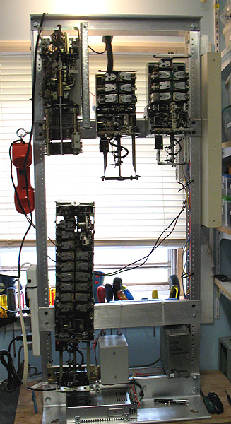
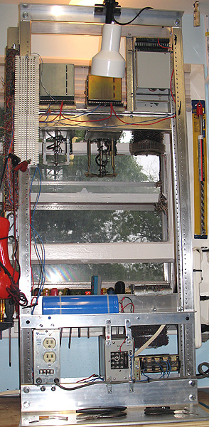
So, without step by step descriptions of the past few days, here is the result!
John, standing next to the just completed switch.
Shown in the photo:
Top row, Fusing and Alarms, L/co relays, Call counters.
Next row: Control Relays, Linefinder (First Selector), and Start Relays.
Left hand side of rack: Microprocessor controlled Cadence Generator (Interrupter) and Tone Generator (mounted on the side of the rack).
Bottom Row: 2 Selectors and Connector (Final Selector).
Back of rack: 7 amp. 48 VDC switching power supply, 1 amp p.s. for call counters, dial tone generator and ring generator.
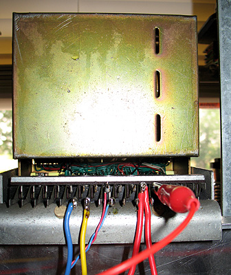
Here is a photo of the microprocessor controlled cadence generator:
Finally after a lot of work, it all came together. Here is a YouTube video of the switch in operation:
Museum C*Net VOIP Project!
I am preparing to connect either this system, or one of the other museum systems to C*Net via Asterisk....It would be nice to be able to let other collectors call into the museum systems from their homes. An update on this project follows:.
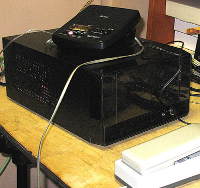
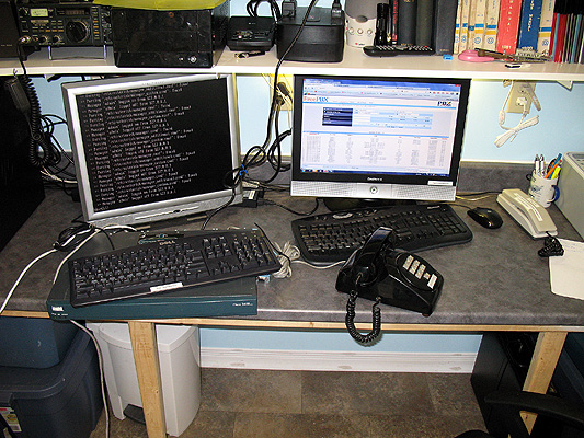
May 05, 2012 - Atom ITX PC based linux/asterisk server providing VOIP service on C*NET, a worldwide network of telephone collectors and museums. This system will allow all collectors and museums worldwide on the network to access and operate the museum's various switches unsing the VOIP protocol. Shown on top is the answering machine which provides answering/messaging through the Panasonic 616 KSU. One calls the first line in the system, and they get an announcement about the museum, and can leave up to 40 minutes of messages. This system was put into operation May 5th, and over that weekend received calls from over 35 collectors and museums from Canada, the US, the UK, Ireland, and Germany in its first 48 hours of operation. Likewise, I can call any collector who is a member of C*NET without charge. This unit was donated by Dean Clark who also advised me durring the set-up stage.
May 11, 2012 - a UPS was received to protect the server from power bumps and outages. Living in the country, one quickly learns UPS protection is a good idea. As this system will run unattended, the UPS will protect it at all times.
Aug 07, 2012 - Sunday, in a marathon phone call, Chad Perkins, John Jones, and I worked on the router and server shown above (router temporarily under keyboard).It will be used with my North American Strowger Demo unit, and when the British unit above is complete, it will control calls into it, too. We now have it calling in, but of course, only when I have the N.A. demo turned on.
One thing I did when I built up the North American Strowger Demo rack back (6 years ago) as I was reminded about Sunday, is I had never hooked up the interruptor - I think it gave Chad and John quite a surprise when they called in to constant ring tone :-) Sunday evening I remedied that, finally connecting the interruptor which has been on the unit for 6 years but never hooked up!
We have a few more bugs to work out, but in a day or two will put the switch on-line for a few hours so people can play with it, Number for line 1 is 1- 651-3211, and for line 2 is 1-651-3212. You can also call in to the Cisco Router FXS Port 1 at 1- 651-5110, a 1500 set. The museum announcement.message system is on 1-651-0001, and you can reach me any time I am home but not in the museum at 1-651-2762. All numbers must be dialed from CNET.
Saturday August 11th, I will have the demo on-line from 7 am until 2 pm Atlantic time so people can experiment with calling in to it. Hopefully all will go well.
Update Aug 11 - Today's on-line test was a success with about 45 calls in to operate the demo. The furthest call was from New Zealand with several calls also from Ireland, Denmark,and Europe. The last 4 digits were passed to the router by the Asterisk server, and the router converts the last three digits to pulses and passed them to the demo unit, allowing people to connect to phones on the actual N.A. Strowger Demo unit. There is some room for improvement, and I hope to increase the amount of time the Demo is on to at least whenever I am in the museum.
The trickiest thing was interfacing the FreePBX with the router -- made more difficult by the FreePBX GUI, and even more by the fact the entire process was entirely new to me. However, with Chad, John, and Dean's help, it is a done deal.