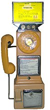
Converting an A/E 3 Slot Payphone for Home Use
Member: Telephone Collector's International 2003/2004
 |
A couple of years ago, I purchased
and received my first 3 slot pay phone. After searching, I found nothing
on the web detailing the conversion from coin operation to home operation
for this and similar phones, so I thought I would pass along these notes.
The phone I converted was an Automatic Electric LPB 82 prepay phone, but
these notes could be applicable to other similar phones, including some
50's era Northern and Western Electric 3 slot phones.
See my Northern/Western Electric 233G and Northern Electric QSD3A Pages! |
 |
Please don't misunderstand, while I have worked on many non-pay phones, I am no expert on payphones, in fact I am quite the opposite, but learning. However, this conversion went off very well and was 100% successful. Follow these directions at your own risk. These instructions assume you have a similar phone which is properly functioning as a payphone to begin with. Replace any needed components first. It is my hope that this at least will provide you with some needed guidance if you, like me, had never done a conversion on a pay phone before. With the absence of information on converting these phones on the net, it was necessary to "fly by the seat of my pants" with some guidance from others.
The phone in question was an Automatic Electric LPB 82 55 pre pay phone, similar in many ways to some Northern and Western Electric models. There are many variations in payphones, even within one brand. A close examination of the phone should determine whether any of these notes will be applicable. Since completing this phone, I have seen a couple of phones identical on the outside, but which varied greatly on the interior due to upgrading during the 70's by different refurbishers. This, however, will give even the owners of such phones a place to start I hope.
The Beginning:
Once you have finished the cleaning of the phone, you are ready to begin. First, unlock and remove the top front case of the phone. Once unlocked, tip the front bottom portion of this section out, lift up on it slightly, and it will come clear from the backboard and lower housing. Unplug the wiring harness where it connects to the backboard (some phones may have metal fingers which mate with contacts in the housing to perform this function without a need to manually unplugging the harness). Set this assembly aside for now.
The first step is to determine where the phone line connects, then to connect the line cord.
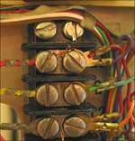
Lay the backboard/base assembly on its back. In the middle of the backboard, you will find a multi-terminal terminal strip (at least in the A/E). You will note that the top three terminals will be marked L1, G, and L2. These correspond to your line cord connections. If it is another brand of phone, look for similarly marked teminals or for remnants of the old line in for guidance. You will require a spade to modular line cord, or a spade ended line cord and modular adaptor. Connect the red of your line cord to L1; yellow, or ground to G; and the green to L2. Using a strain relief, secure the cord so that it will not pull loose from the phone. Run the other end of the cord out through the oval hole next to the strip.
Step 2:
You can reconnect the front section at this point, and see if it will dial properly. If a 50's or later phone, it likely will not, for reasons mentioned below. If not, remove the upper portion again and set it aside.
What causes this inability to dial, is that in later 3 slot phones and those which have been retrofitted, the dial was intentionally shorted until coins were deposited to prevent people from sticking a pin through the handset cord, or into the microphone and touching it to the booth or other exposed (grounded) metal to get a dialtone, and being able to successfully dial (payphones used lines that didn't give a dialtone until a coin was dropped in, and a ground was placed on the line through the coil). It was a simple fix to solve the problem of people getting free calls using this technique. So what you are experiencing is normal behavior for the phone. In order to use it on non-pay lines, you must disable this feature.
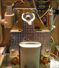
This dial shorting on this phone was accomplished by adding an extra set of contacts to the coin relay - look for a large coil in front of the backboard section of the case [see photo, right]. These contacts are located on the rear of the relay. By removing the top wire from this second set of contacts, we eliminate dial shorting, so the phone may be used without depositing money. On the A/E, the shorting contacts are the set furthest back from the coil, and the wire to remove in the case of my phone was red. I am told that in Western Electric phones, the wire may be green.
If on other phones this fails to allow dialing, try replacing this wire and removing the top wire from the first set of contacts.. Make sure you insulate the terminal lug on the removed wire so that it won't cause problems later. It is also a good idea to label this wire as to where it came from, in case you wish to revert to the original configuration later.
On some models, particularily this one, if you find a microswitch in the back of the upper front housing (mounted on the coin channel and directly above the dial), it may be necessary to clip one of the two leads. This switch will also short the dial. I discovered this after performing the above step - occasionally, this switch would move into the on position, which would short the dial. It is easy to fix by manually setting it in the off position, but a better, more permanent solution is to disable it.
Step 3:
Almost there. You will want to set the phone so that coins that are deposited go either directly to the coin box, or, as I chose, to the coin return. This will prevent the coins people will inevitably deposit in the phone (Naw, they wouldn't do that, would they?) from building up and clogging it. If you wish to use the phone as a bank, send the coins to the coin box, otherwise, send them to the return.
How do you accomplish this? Well, at least in the case of the A/E, easily. If you reach in from the side of the coin channel from the left, you will feel a little flipper vane inside. In one direction, it sends the coin to the coin box - in the other to the return. If you wish to send coins to the box, merely push in the coin relay, and tie it in the closed position with a nylon wire tie. If you wish to send coins to the return, manually move the vane to the return side, then do as above while holding it there, tie the coin relay in the closed position. [See photo of relay, above right].
Note: Incidentally, the above trick of tying the coin relay will work on the more modern Centurion payphone's relay. However, in that case, tying the coin relay closed will automatically shunt the coins to the coin return.Clean up after your work, reinstall the top portion, and test for operation without coins. It should work without coins and allow dialing, and any coins deposited will come out the coin return or go into the coin box, whichever you selected.
As you insert coins, you will hear a single bell whenever a nickel is fed into the phone, two rings for a dime, and a deep gong when a quarter is inserted. By counting the sound of the coins being inserted, it was possible for the operator to know the customer had fed the required toll into the instrument.
Often I have seen in eBay ads people saying that a payphone's ringer doesn't work. This is something I get a kick out of - many these phones did not have internal ringers as manufactured, but if desired an external modular ringer may be used to add this feature. One possibility for adding an internal ringer might be to hide it within the coin compartment if the coin box is left out, however, if one wished to do this, there should sufficient space if located carefully inside the upper compartment. Have fun, and enjoy!
My thanks to those who gave me advice on this project: Mike Davis, Gregory Stewart, and Fred Haynes. If anyone else has any ideas or suggestions on restoring these phones, or who has payphone wiring diagrams, I would love to hear from them, and publish their suggestions or schematics here to assist others!
I have been asked several times which locks fit this phone. Until recently I would avoid the answer, as I really was confused over the various lock numbers available. However the proper top lock for an AE 3 Slot is a 29S, and the correct coin box lock is a 10L. Just a little tidbit which might help someone out!
Automatic Electric 3 Slot Payphone Instruction Card:
This is a scan of a mint original A/E 3 slot payphone instruction card which was found under the telco instruction card of my pay phone. Print it out in your highest print quality on satin photo quality paper. Use a rubber stamp kit (e.g. Tro-Dat�) to print the numbers on the cards once printed. Trim, and install in your center card holder.
- This file is 357k in Adobe PDF format, which will print out the proper size, approximately 4x4". It will require the Adobe PDF reader. Contact me by email if you wish to receive this PDF file - [email protected].
See our "Northern/Western Electric 233G", "QSD3A", and "Centurion" Conversion Pages!