| Party Lines! | Pioneers! | Rural Companies! | On-line Museum! | Links! | Comments? | Home! |
Conversion Of A Northern Electric 233 Payphone for Home Use
Member: Telephone Collector's International

|
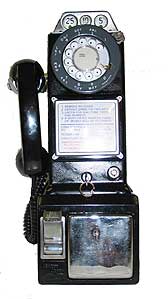
This is a Northern Electric 233 payphone I recently received. On this page I will detail my experiences with this phone and share notes on repairing and refurbishing this phone. The NE233 was widely used on Prince Edward Island and the rest of Canada. These notes will also be applicable to the Western Electric version of the same phone used extensively in the United States. | 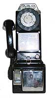
|
This is my second 3 slot payphone conversion project - restoring and converting a Northern Electric 233 payphone for home use. The 233 was the payphone of choice for many years here on Prince Edward Island, and could be found in booths around the Island. This is a more complex conversion than that of the Automatic Electric payphone, as the 233's in their natural state had no internal network, and were used with an external 685-A subset. The phone would be connected to the subset via a wire exiting the phone, and the subset mounted below. In order to work on a phone line, a subset and/or network must be provided.
Working on a phone like this be like following a path with many twists and turns. Many have been modified many times during their working lives, and if previously converted, you could run into anything. Complicating the process, the phone had been damaged in shipping - a chunk broken out of the handset hook on the left hand side, and the front of the dial smashed in and the dial damaged internally. For the photographs, taken before repair, only the plastic fingerwheel was replaced - the broken hook doesn't show due to the angle of the shot. Both have to be replaced before continuing onward. The gentleman I purchased the phone from was very helpful, cheerfully replacing the damaged parts. An additional issue to me was that in order to mount a ringer in the phone, the coin relay had been removed. I guess I am a bit of a purist, but I did want the relay in the phone - the vendor also quickly provided a replacement.
Before I go any further, I want to credit the vendor of the phone - he went above and beyond the call of duty, and deserves special mention. He is Don Woodbury, a schoolmate and neighbour of mine when I was young. Don now runs a company named Old Phone Works with a number of locations in Eastern Ontario, Canada, and carries an extensive line of refurbished vintage telephones. He has locations stocking antique phones in Kingston (2 stores), Brockville, and Lindsay, as well as two service locations in Orillia and Peterborough. I recommend Don highly. I have purchased phones and parts from him on several occasions, and was very pleased with every transaction. Visit his site via the link given to view phones available from Old Phone Works.
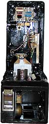
If you are familiar with the 233 pay station, you will note a number of modifications in the phone as received in the photo to the right. A stock 233 has no internal network, and no internal ringer. Use with some form of network is essential to use this phone on home lines. Additionally, there are several wiring changes which need to be made allowing it to get dial tone without inserting a coin first, and to eliminate dial shorting.
On this phone as received, an ITT network had been mounted in the top of the phone where normally a terminal strip is mounted, and extensive wiring modifications from original had been made. The coin relay had been removed to add an internal ITT ringer. I am going to replace the coin relay, and move the ringer down into the unused coin box area, and set the phone to shunt all coins dropped into it back in to the coin return rather than the coin box as I did in my Automatic Electric Payphone conversion. I find this most convenient as you don't have to unlock the coin box door to remove the coins inevitably deposited by those experimenting with the phone. Believe me, they will deposit coins in the phone.
The first step in the restoration is the replacement of the broken dial and broken switch hook. As I replace these, I will include notes on how this is accomplished. The NE233 is a very easy phone to access for repairs. Please use the following notes for a guide only. Make changes in your phone at your own risk.
The Dial:
Replacement of the dial assembly, a project which at first glance would appear difficult, is going to be suprisingly easy if your phone is stock - mine wasn't.
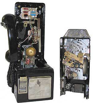
First of all, open the phone up as shown in the right hand photo above. You will note the upper coin channel and mechanism. To access the dial, one must remove the coin mechanism. To do this, remove the two tall bolts with their surrounding springs. Remove the screw from the lower left end of the mechanism. Remove the L-shaped bracket from the right hand side of the case. Lift out the coin assembly up and back and set it carefully aside.
You will then see the dial assembly below. On the sides, and on the bottom of the dial assembly, you will see three screws. Remove the nuts and washers from the side screws, and remove the lower stud, also the L-shaped brass strip that bends over the dial. Now, if you lift slightly on the front dial shroud, the dial can be easily removed. Re-installation, is the reverse of the above. When replacing the coin mechanism, tighten the spring bolts to the point where they just stop turning. If this isn't done, the coin return will not pop back out when pressed.
While working on the dial, I discovered the phone had been rewired in a major way. I knew it had been modified at least as far as the network and bell were concerned, but wasn't totally aware of the extent of rewiring. That point came when I noticed the dial had only 4 leads, as opposed to the 5 normal for the phone. I drew a schematic of the internal wiring of the phone as I received it, and compared it to the original and noticed some very major differences, all introduced apparently when the ITT network and ringer were installed.
As wired, there would be a difficulty in using an original replacement dial as the contacts and required wiring did not match. By using only the "On" contacts and "pulse contacts" in a similar to normal #6 but gold faced dial, I was able to make it work properly with the phone's modified circuitry. As mentioned above, a "proper" dial is coming for the phone, and I wanted to make see if I would be able to get the proper dial to work in this modified configuration - it won't without extensive rewiring back to original. This temporary replacement had one more terminal than the proper dial, allowing its operation with the modified circuit, but not with the proper 5H dial. As it is now, with the temporary replacement, the phone dials and receives calls normally, but the phone will need to be rewired correctly to work with the proper dial.
I will be restoring this phone to its normal wiring and configuration so this will become a moot point in the future. As for installation instructions, though, they remain the same as above - the only difference being that the normal unmodified phone would have 5 leads from the dial - this one only 4.
The Switch Hook:
If you need to replace the switch hook arm, begin by removing the upper section. You will see the switch hook assembly mounted on the backboard just below the top terminal strip (in this phone, the network). Locate the small hex bolt in the end of the switch hook arm extension, closest to the switch contacts. With a pair of pliers, remove this bolt. Slide the switch actuating assembly off the end and to the side. Above the spring, and under the actuating assembly, you will find a small flat slotted screw. Remove this screw completely. With a little gentle persuasion the old switch hook arm will slide through its bearing, and out the side of the phone. Slide the new switch hook arm back through the bearing, and into the arm extension, checking to make sure the setscrew hole lines up with that of the extension. Replace the setscrew and tighten. Now, replace the switch actuating assemble, ensuring that it properly engages with the milled slot on the end of the switch hook arm extension. Replace the small bolt. Check for normal switch operation. Replace the top section, and test for proper operation. In the unlikely case you do have any difficulty, it is likely that you haven't got the switch actuating arm located properly within the switch pileup. It should be located within the "U" - shaped portion of the switch pileup.
The Coin Relay:
In most cases, you won't need to replace the coin relay and lower coin channel, but if you do for some reason, instructions follow. The coin relay is relatively easy to replace. In this instance, I replaced both the relay, and the lower coin channel as they arrived in one piece, and it was easier to replace them both together than simply to install a new relay and miscellaneous parts which connect it to the channel.
To do this, open the phone, and remove the top portion. Open the coin door. Note the location of the wires connected to the relay, then disconnect them. There are 4 screws that enter the lower coin box area from the rear of the backboard. Remove them to separate the lower portion from the backboard.
Now, if you place the lower portion on its face on the level and look in from the back towards the top, you will see the 3 screws holding the relay, entering directly below the relay. Remove these and save them. Lift off the coin relay/lower channel, put the new one in, and reverse the steps outlined here. Replace the wires as they were before the substitution of the new relay. On this phone the replacement of the relay was necessary since there was no relay installed when I purchased the phone. The relay at some time had been removed to accomodate a small single gong bell. As the whole assembly was available, I decided to replace relay and lower coin assembly.
During this process, the bell was moved down into the coin box area out of the way of the relay. Wires from the bell were routed through existing holes and reconnected.
Moved into Coin Compartment
By default, all coins deposited in the phone will fall to the coinbox area. If you wish to shunt all coins deposited into the phone into the coin return instead, reach into the throat of the coin channel from the left. There you will feel a plastic flipper vane. Hold this in the direction of the coin relay, hold the relay armature in, then tie the armature so that it will stay in that position using a plastic wire tie around the top portion of the relay. Once done, the vane will stay in this direction, and deflect all coins back into the coin return until such time as you untie the armature (note black tie on the top of the relay in photo).
Rewiring:
This can call for differing levels of complexity depending on what you plan to do with the phone, and what you have to work with to begin.
First of all, and common to most conversions, the phone must be modified for coinless operation, and dial shorting removed. There is an alternative to this, the construction and use of an external payphone controller, but on all applications not using a controller the following steps must be taken:
Step one, remove the yellow ground wire going to terminal G (hopper trigger contact) in the phone. Second, a jumper must be installed from terminal L to terminal T. Finally, the wire leading to terminal 1 on the coin relay must be removed to eliminate the dial shorting. See my Automatic Electric payphone page for a description of what dial shorting is, and why it was used. A network must be provided.
Provision of a Network:
Note that a network must be provided, whether an internally mounted network, or an external 685A network as would have been normally used with this phone. This phone is what is called a stand only and contains no internal network parts, and the 685A network/ringer is normally connected outside of the phone.
Stan Schreier in a recent article on the ATCA (Antique Telephone Collectors Association) site, shows how a more modern network may also be used, e.g. one from a Contempora phone, or an ITT 427 or 1427. Using the same connections, a 425A network from a scrapped 500 set may also be used. In his article, Stan shows the connections to Contempora, ITT 427 or 1427 networks. See Stan's article by clicking on the ATCA link for more information on using a modern network. A small network can be hidden in the coin box of the phone to avoid extensive modifications to the phone, and is removable so that the phone can be quickly returned to its normal state.
Locks and Keys:
The Northern Electric 233 uses an NE-22 lower (coin door) lock, and an NE-21B upper lock. Do your utmost not to destroy the upper lock. The NE-21B upper lock is universal - NE21B keys for this may be ordered from a number of sources, including Phoneco in Galesville, Wi. To ask about ordering keys and locks, use the "Questions or Comments" form provided on their page - locks are listed on their catalogue pages, the keys aren't. The same is true of upper locks only for 3 slot payphones manufactured by Western (10-G lock and key) and Automatic Electric (29-S lock and key) as well. Just state what manufacturer of phone you have - they will do the rest. Another source of upper lock keys is Customphones in Indianapolis, In.
If you know someone who has a similar phone, their key should open the upper section for you while you await your key. If you try an NE21B key, and it fails to work, also try a WE10G key - the lock might have been changed at some point in time to a Western Electric. They are, other than keying, interchangeable.
My upper lock is broken. Now, how do I det the darn thing open? I ran across this in the case of my QSD3A - its lock was hopelessly rusted, and even with the correct key it couldn't be convinced to open. While I don't personally recommend this procedure, it will work if done carefully - only try it if you have previously obtained the correct upper lock key and it doesn't work. Pad a wide flat bladed screwdriver with cloth, and place it in the crack between the upper and lower sections. Pry gently. With luck, this will allow the two sections to separate. Be very careful and apply only moderate force - it is possible to crack the castings doing this. The upper lock can then be removed and replaced with a working one. This should be used as a last ditch attempt only.
Now, how do you open the coin door if you don't have a key for it? Lower locks (coin door locks) on all 3 slot phones are individually keyed, regardless of manufacturer.
First of all obtain a key for the upper lock, and remove the upper section of the phone. Note the location of the wires going to the coin relay then disconnect them - these can be reconnected later. Then with a large screwdriver, remove the screws which hold the lower box to the backboard. If there is no coinbox in the phone, you will then be able to access and remove the lock from the backside of the door by unscrewing its 4 bolts. These may require a long hex driver to remove depending upon the bolt type used. A new lock complete with key may then be used to replace it, as chances of finding a key to fit your existing lower lock are slim. These may also be ordered from Phoneco (complete doors complete with lock and key also are available).
If there is a coinbox in the phone (most often they aren't), you will not be able to access the screws holding the lock by doing this. If you know a friendly neighbourhood locksmith or felon, let 'em have a go at it - should they fail, follow these instructions at your own risk: One way to open the door is to very carefully drill out the tumblers of the lock with a titanium drill bit. Once the tumbler is out, the slider of the lock can be released. The metal in the tumblers of these locks is very hard. They were made for security, not for ease of opening. Start with a small bit, then graduate up to a larger bit. This must be done carefully to avoid damaging the door. Taping the area surrounding the lock with a few layers of masking tape may help reduce the risk of scratching the door should the bit slip during this procedure Remove the lock and replace with a new one with matching keys.
Another suggestion with merit is to use a hammer drill on the lock with a blunt bit - try this first! Once again, tape carefully around the lock. This will vibrate the nuts holding the lock on and they will vibrate off. This idea has definite merit, as with the last method, drilling the lock, it requires a lot of fiddling still to get the lock released. This merely drops the lock off inside the phone and allows it to open!
Remove the lock and replace with a new one with matching keys.
Documentation on these phones is difficult to find. though in the 60's there were many thousands in use. Barring the availability of BSP's (Bell System Practices bulletins) and NEP's (Nothern Electric Practices bulletins) for this phone, it would be difficult for a beginner to get one of these phones operating. Steph Kerman has kindly sent me a PDF copy of the original BSP schematic of this phone to compare with the phone as received. I hope this page will serve at least as a guideline for those attempting such a conversion. The 233 is a great phone - even better when it can be used. Do not attempt these modifications if you do not have at least a good basic understanding of telephone circuitry, and then do so at your own risk. Remember, that if you are going to connect the phone to telephone lines, it must be done properly, and connections must be made through a proper network. While you can own your own equipment, the telephone company owns the lines from your protector/demarcation point outward, and you can be held responsible for any damage to telephone company property.
Also see my "Northern Electric QSD3A", "Centurion", and "Automatic Electric LPB 82" Conversion Pages!

| Party Lines! | Pioneers! | Rural Companies! | On-line Museum! | Links! | Comments? | Home! |